I wanted a silent, remotely monitored and controlled printer that would produce high quality prints while still keeping a tight physical footprint. This is how I got there.
I've recently overhauled my two stock MPSM V2 3D printers. The changes include:
* replacing the stock M200_V2-MAINBOARD with SKR 1.4 board with 2208 stepper motor drivers.
* adding a controllable parts cooling fan.
* adding Octoprint via GPIO
* adding 2 channel wifi power control with additional local button control.
* adding local buck power converter to power the Raspberry Pi
* adding local electronics fan temperature controller and an additional electronics cooling fan.
* adding daytime/nighttime IR-Cut camera.
* adding remote monitoring via Octoeverywhere and Printoid.
I purchased two used MPSM V2 printers on Ebay for about $70 each. I wanted to increase my printing capabilities and was also looking at the Prusa Minis. But at $400 each for the Prusa Mins, I thought I'd get far better mileage and learn a lot more by overhauling existing used printers. I also wanted remote monitoring and control, which the Prusas did not come stock with. For the MPSM printer overhauls, I figured the approximate changes would cost me:
$155 for the two printers.
$45 for a RPI 3B+
$0 for the RPI 3B+ that I already had
$35 for a SKR 1.4
$0 for a SKR that I already had
$25 for 2208 stepper motor drivers
$0 for for 2208 stepper motor drivers that I already had
$6 for two untested temperature controlled fan controllers
$40 for two IR-Cut cameras (in a separate post)
$5 for two 30mm axial parts cooling fans (in a separate post)
$5 for two 40mm axial electronics cooling fans
$14 for two untested 2-channel wifi controllers
$10 for various buck converters, USB solder ends, etc.
So, about $350 for the two machines.
I would also have to design mounts for the electronics, solder components and test some new-to-me stuff. I'd also need to compile new firmware.
The 3D files can be found on my Thingiverse post: https://www.thingiverse.com/thing:4871193
Please note that these files are too large to be printed on a Mini.
Disclaimer: I barely know what I am doing and am not entirely sane. I'll do my best to document and show everything I did and how it can be repeated, but this work is dangerous. Hazards include: Bricking any and all electronic components, destroying your 3D printer, death, dismemberment, insanity, and possible disruption to the time/space continuum. Proceed at your own risk.
Those who wish to follow what I have done should:
* Be well-versed with 3D printing
* Have intimate knowledge of how to customize a 3D printer
* Be experienced with soldering and electronics; be already equipped to solder and have electrical connectors like Duponts and whatnot.
* Know VSCode and how to manipulate firmware
* Have a quality set of tools and parts for 3D printers. Aside from reusing the stock black screws, I mostly used 3mm screws, maybe 4mm, 6mm, and 8mm in length. Heck the fan screws might be 12mm.
* Not be entirely sane
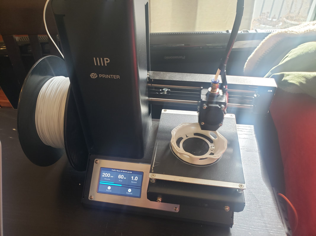
A stock Mini V2. Works great! But, loud, requires files to be loaded via card, no Octoprint, and no parts-only cooling.
Overview
I have a couple of years of experience with 3D printing and 3D design, and some printer modifications. I knew this wouldn't be easy, but I was also not prepared for this to be a major learning experience.
I started with the basics, learning everything I could about the machines, including reading and watching several upgrade tutorials. I went through all the literature I could find. I tested my current machines to make sure the mechanicals were sound. Then, I sketched out a plan on paper of what I wanted and how I would connect everything. I started searching for components that would get me the solutions that I wanted. Some of these I had not heard of before, so I knew integration might be risky. I made a list of what I needed to buy and assembled my parts. Then I wondered, Would they all fit inside the existing electronics case?
I started with the basics, learning everything I could about the machines, including reading and watching several upgrade tutorials. I went through all the literature I could find. I tested my current machines to make sure the mechanicals were sound. Then, I sketched out a plan on paper of what I wanted and how I would connect everything. I started searching for components that would get me the solutions that I wanted. Some of these I had not heard of before, so I knew integration might be risky. I made a list of what I needed to buy and assembled my parts. Then I wondered, Would they all fit inside the existing electronics case?

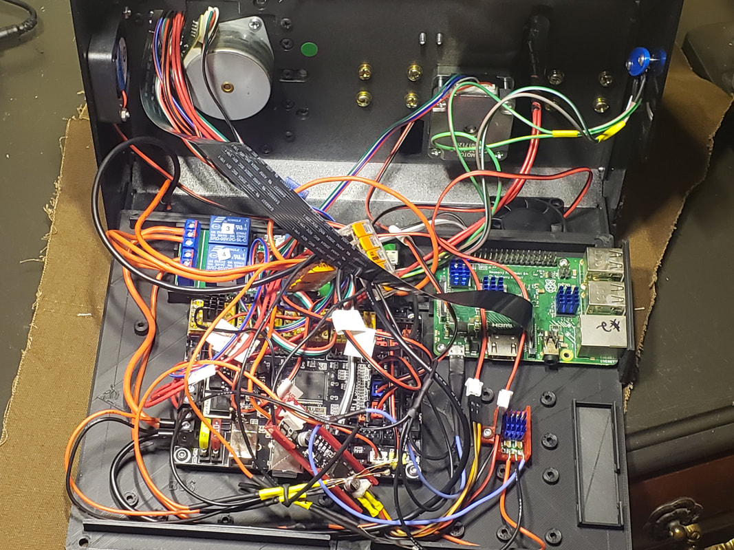
Will this stuff fit? If so, how?
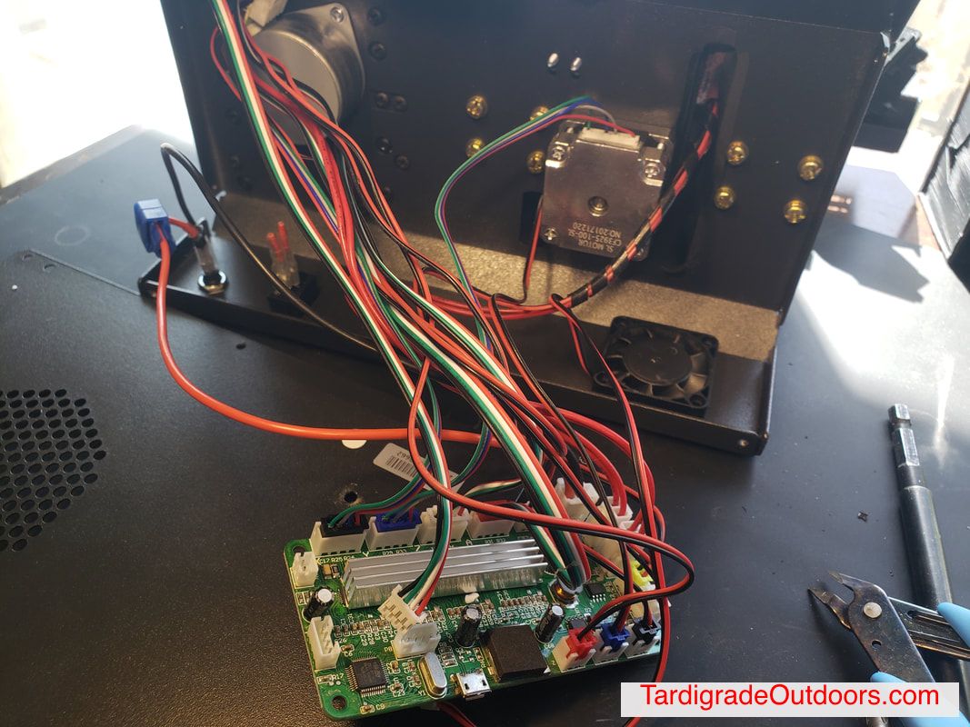
I cracked open the electronics enclosure and removed the motherboard and display, carefully disconnecting the wires and labeling anything that wasn't obvious.
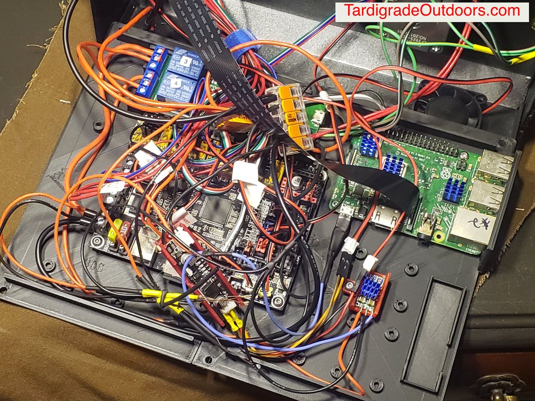
I set the SKR 1.4, RPI, wifi controller, fans controller, and buck converter on top of the Mini's bottom cover. I knew I wouldn't be reusing the posts, so I wiggled them back and forth until they broke loose. I arranged the electronics, took some measurements and made a new set of plates that mounted everything. This new plate could sit on the old bottom cover.
I set the SKR 1.4, RPI, wifi controller, fans controller, and buck converter on top of the Mini's bottom cover. I knew I wouldn't be reusing the posts, so I wiggled them back and forth until they broke loose. I arranged the electronics, took some measurements and made a new set of plates that mounted everything. This new plate could sit on the old bottom cover.
I made up a sketch of how I wanted everything to be wired. As I had two machines, I sort of bounced back and forth with new layouts, parts, and wiring to be tried out.
I wired up the wifi controllers, buck converters and fan controllers and tested them. I'll touch on each of them in this post.
I wired up the wifi controllers, buck converters and fan controllers and tested them. I'll touch on each of them in this post.
Once I sketched out how everything was to be wired and placed (I'll post the sketch when I get back home), I started on the 3D modeling of the skids. I was able to import some of my old work, which is a very useful trick that I have learned. The bottom plate was too large to be printed on my Ender, so I split it in half. One should probably print out the parts needed, just so stuff can be mounted as it's completed.
I'm going to divide up this post into the major parts:
* Power wiring
* Electronics enclosure fan temperature controller and fans
* Wifi controller
* Buck converter for the RPI
* SKR 1.4 & 2208 firmware
* Serial connection between the SKR 1.4 and RPI
* Future work
I'm going to divide up this post into the major parts:
* Power wiring
* Electronics enclosure fan temperature controller and fans
* Wifi controller
* Buck converter for the RPI
* SKR 1.4 & 2208 firmware
* Serial connection between the SKR 1.4 and RPI
* Future work
Power wiring.
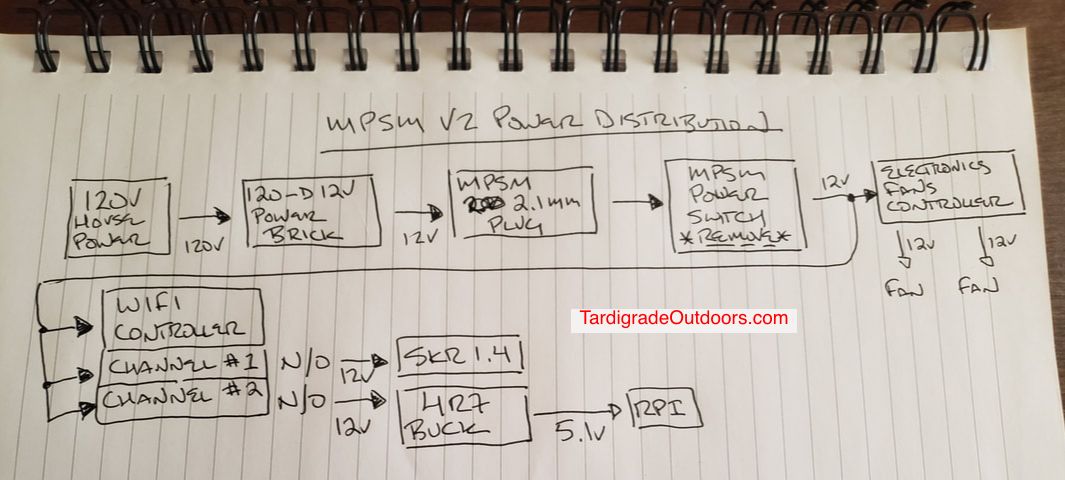
This is an overview. The stock power brick remains. But, I since I bought my Minis used, YMMV. Upgrade if necessary to 12V/10A. From there, I soldered longer wires onto the 2.1mm jack on the Mini. The stock power switch needs to be removed or replaced, it cannot handle the power. I've melted three already. The rest I'll expand upon as we continue, part by part.
The electronics cooling fan temperature-controlled fan controller.
I hope I worded that right.
I hope I worded that right.
Wire the two fans like in the photos and, if there are any doubts, I'll include another sketch. The controller can be found on Aliexpress here and here from the same company I used, or try a search for "DC 5V 12V PWM Speed Controller Fan Speed governor" or look for something that looks the same with the same specifications. But, if you buy something slightly different, it may not fit into the skid on my Thingiverse page.The additional fan bolts to "B11 MPSM West Cover" with 3mmX12mm bolts and nuts Face this fan to blow outward, as the stock fan blows inward.
Use a multitap to connect it to incoming power. I used standard DuPont connectors and flexible silicone insulated wires to connect to the existing fan connectors. The programming instructions are insane, so I generously included some that are slightly less cryptic. Download the file, "fans_controllers_instructions.pdf". I set mine to "2, 2, and 2" because it seemed reasonable, YMMV. The controller snaps into part "B11 MPSM Ele Fan Control Skid", or the one with mounting holes, or the East skid. They're designed to be filed on the inside for custom mounting tension. Place it where you can get to it while printing for adjustment. Good luck.
Use a multitap to connect it to incoming power. I used standard DuPont connectors and flexible silicone insulated wires to connect to the existing fan connectors. The programming instructions are insane, so I generously included some that are slightly less cryptic. Download the file, "fans_controllers_instructions.pdf". I set mine to "2, 2, and 2" because it seemed reasonable, YMMV. The controller snaps into part "B11 MPSM Ele Fan Control Skid", or the one with mounting holes, or the East skid. They're designed to be filed on the inside for custom mounting tension. Place it where you can get to it while printing for adjustment. Good luck.
| fans_controllers_instructions.pdf |
Wifi controller.
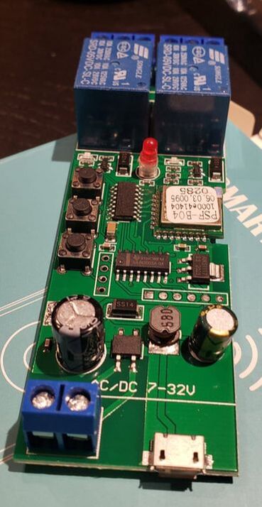 | 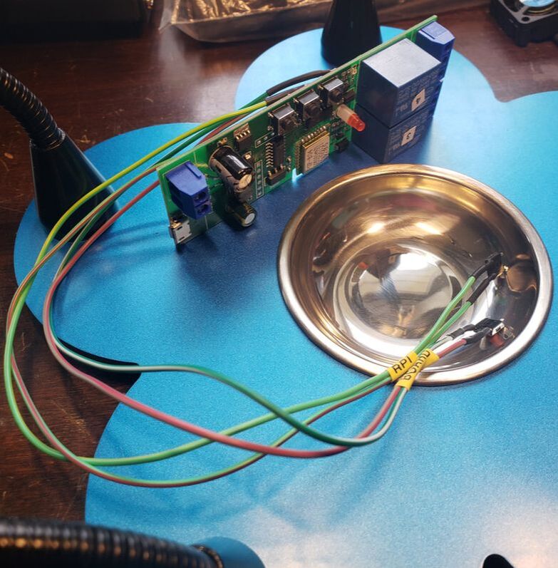 |
This is a 2 channel wifi controller with onboard momentary contact buttons. The two channels are for independent control of the motherboard and the RPI.
I wanted buttons that I could mount on the outside case for local, manual control, so I soldered on a set. I suggest these wires and these buttons (3 mm x 3.5mm x 2mm or 4mm x 4mm x 2 mm will fit fine). I wired the leads to the bottom, as shown. Then, I tested: https://imgur.com/a/TqisBuo. The momentary contact buttons are mounted on the "East Cover" and secured with a "ButtonsLED" mount and 3mm x 4mm long screws. I wired it all via the above sketch. The power to the motherboard should use heavier wires, such as these 18ga wires.
I wanted buttons that I could mount on the outside case for local, manual control, so I soldered on a set. I suggest these wires and these buttons (3 mm x 3.5mm x 2mm or 4mm x 4mm x 2 mm will fit fine). I wired the leads to the bottom, as shown. Then, I tested: https://imgur.com/a/TqisBuo. The momentary contact buttons are mounted on the "East Cover" and secured with a "ButtonsLED" mount and 3mm x 4mm long screws. I wired it all via the above sketch. The power to the motherboard should use heavier wires, such as these 18ga wires.
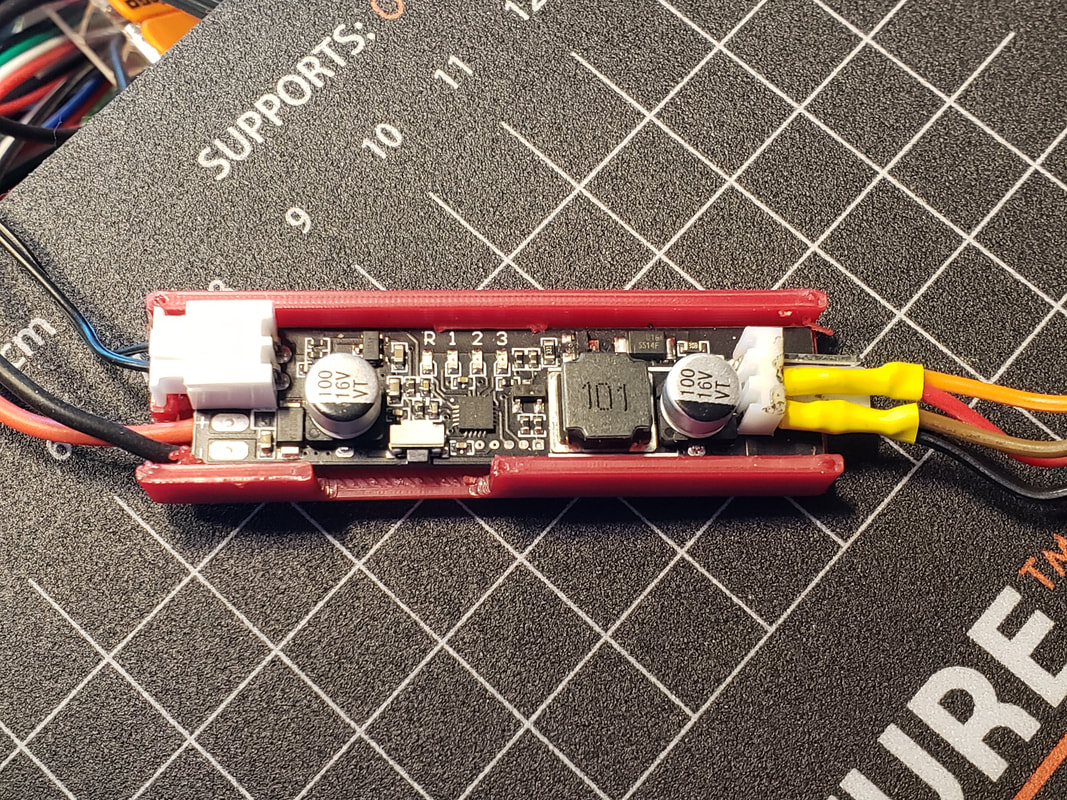
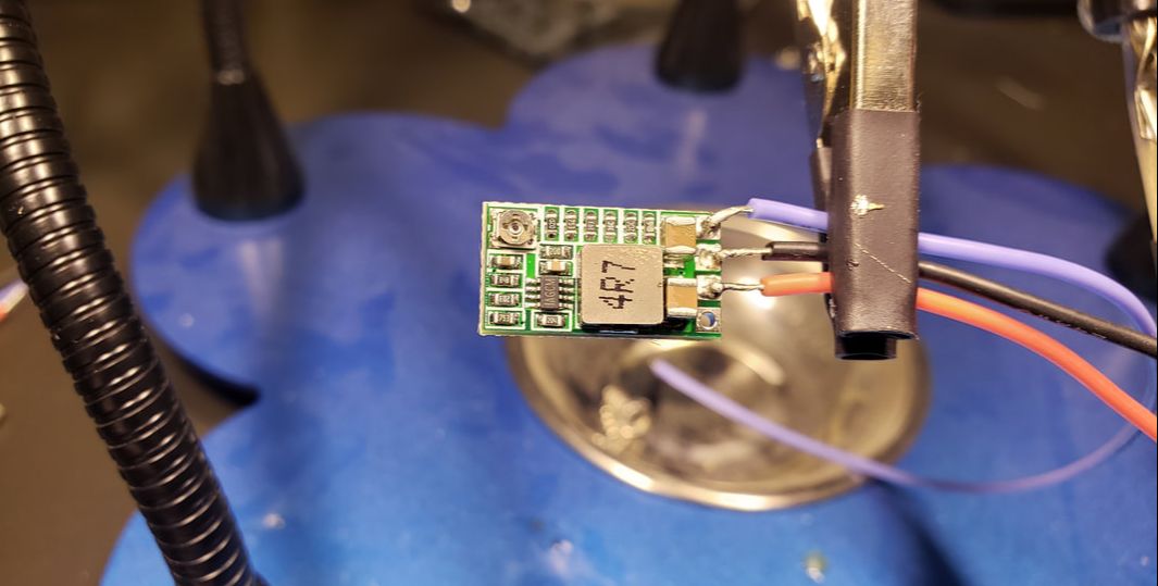
Buck converter for the RPI.
I always provide power to my RPIs via the USB connectors, even if I'm using soldered USB connectors, which I actually prefer. Powering via GPIO bypasses the power regulation and fuse protection and why take that chance when we're soldering anyways? Here is a link to solderable Micro USB connector and USB-C connectors that I have used.
I reduced the voltage coming from the controller to 5V for the RPI using this buck converter. But, beware, the connections are mislabeled! This should help:
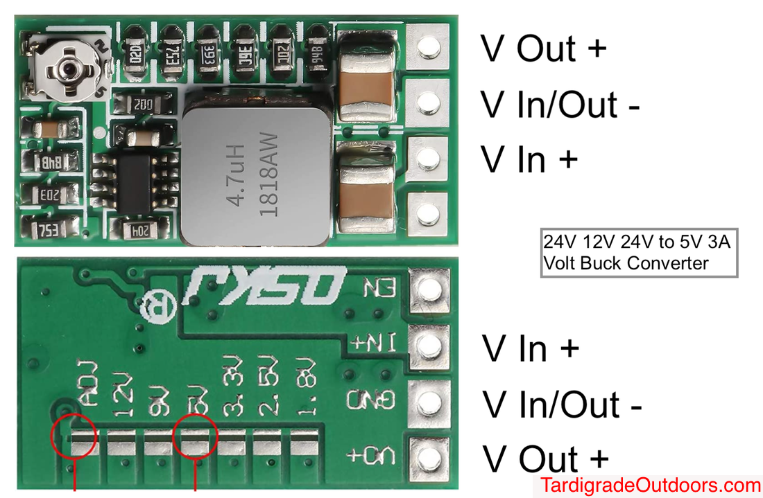
I used the adjustable voltage control to get to 5.1V. Then, I soldered the USB connector. I also put a heatsink on, as specified in the instructions. It is designed to be mounted to "B11 MPSM Mini Buck Skid". They're also designed to be filed on the inside for the designed mounting tension. I then wired it up like in the sketch and mounted the RPI and buck converter on "B11 MPSM East Skid".
 |  |
SKR 1.4, 2208 drivers, and the firmware.
Wiring up and mounting the SKR 1.4 is not a big deal. Same with the 2208 drivers. Follow the manufacturer's instructions and use your vast experience and you'll be fine. You probably already know this.
Compiling firmware is complicated and I hope to share some helpful information on a later post. One should already be familiar with compiling firmware before attempting this. However, I have included a txt here on my changes for reference. YMMV.
| the_firmware_changes_i_made_skr1.4_2208_mpsm_v2.txt |
Serial connection between the SKR 1.4 and RPI
Everything should be mounted to the skids and wired up at this point. I've detailed how to do the serial connect in another blog post.
Everything should be mounted to the skids and wired up at this point. I've detailed how to do the serial connect in another blog post.
Set up Octoprint on the RPI as you would any other. The skid has a little MicroSD card ramp to make installation a little easier.
Heatsinks are cheap, so I put them everywhere. That's pretty much it. Bolt, screw, and connect everything together. Turn it on. Hopefully no sparks.
The bottom skids have little walls to keep the wiring off of the metal bottom of the printer. I've included wire management options. Don't forget to monitor and setup the fans controller after the printer has been running for a while.
The bottom skids have little walls to keep the wiring off of the metal bottom of the printer. I've included wire management options. Don't forget to monitor and setup the fans controller after the printer has been running for a while.
Still, one must calibrate the 3D before printing. I suggest using these guides: https://teachingtechyt.github.io/calibration.html and https://jscalc.io/calc/tHjfIiKMKjDF42Hg
Keep an out for future posts on cameras installation, parts cooling fans installation, mirrored bed installation and some other super-secret stuff.
Videos of operation: https://imgur.com/gallery/izN9Djh and https://imgur.com/gallery/GDcPOEY
 RSS Feed
