 |  |
I think I better understand the key elements of using aftermarket boards after a couple of years of 3D printing and tearing apart my machines way too many times. In this post I'm going to share a little bit of what I've learned from the generous 3D printing community. We're going to detail getting rid of your USB cable. This post expands upon what I wrote about in my previous blog post, "How to print without a USB cable on an Ender 3 and OctoPrint."
There will be three parts to this tutorial to get the basics completed.
* Preparation
* Connecting the Raspberry Pi (RPI) to the motherboard
* Configuring the RPI
* Preparation
* Connecting the Raspberry Pi (RPI) to the motherboard
* Configuring the RPI
Disclaimer: I barely know what I am doing and not entirely sane. I'll do my best to document and show everything I did and how it can be repeated, but this work is dangerous. Hazards include: Bricking any and all electronic components, destroying your 3D printer, death, dismemberment, insanity, and possible disruption to the time/space continuum. Proceed at your own risk.
Preparation.
To get this done, Octoprint must already working with the 3D printer.
1) The motherboard should be a MKS Gen L V2, MKS Gen L V2.1, SKR 1.4, or SKR 1.4 Turbo. These are the only motherboards that this tutorial will cover.
2) The RPI needs to be a 3B+ or better.
3) Three Dupont-connected wires are needed to connect the distance between the RPI and the motherboard. Take an approximate measurement of the length needed and search an online retailer for "Dupont jumpers". The female-female jumpers are needed.
4) The needed pins, shown below, cannot be presently used for anything else.

Female to female Dupont jumpers
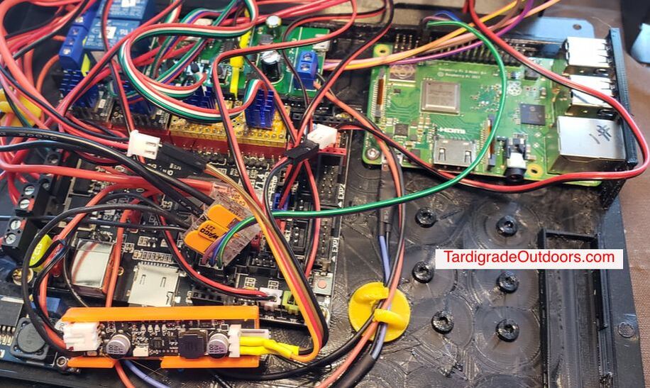
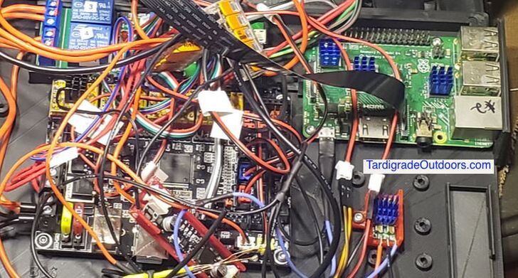
Connecting the Raspberry Pi (RPI) to the motherboard.
Disconnect power from the printer and remove the USB cable and access the RPI and motherboard. If power is not physically disconnected, injury and/or damage to equipment may result.
On the RPI, connect one end of each of the three jumpers to 6 (GND; ground), 8 (TXD; data send), and 10 (RXD; data receive). The pinout for our purposes here are the same for the RPI 3 and RPI 4.

RPI 3 and RPI 4 pinout
Next, connect the jumpers to the motherboard. GND to GND, TXD to RX, and RXD to TX. Locations will differ, depending on your motherboard, so reference the pinouts below.
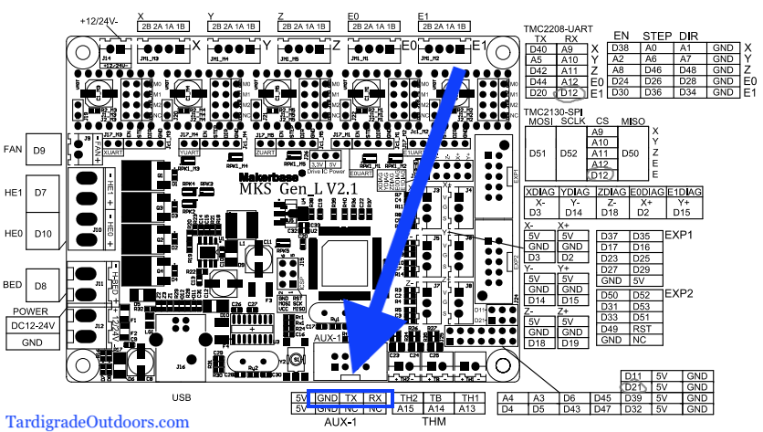
MKS Gen L 2.1 pinout
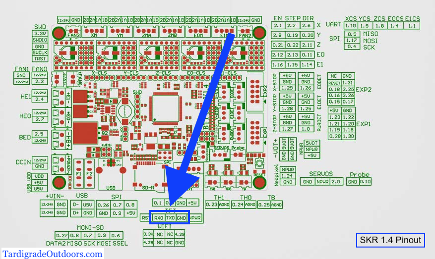
SKR 1.4 and SKR 1.4 Turbo pinout
Configuring the RPI.
Power up the RPI and access the config file. Information on how to access the config file can be found here: https://www.makeuseof.com/tag/edit-boot-config-file-raspberry-pi/.
Navigate the config file thus:
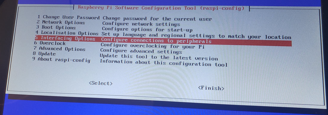
Select Interfacing Options,
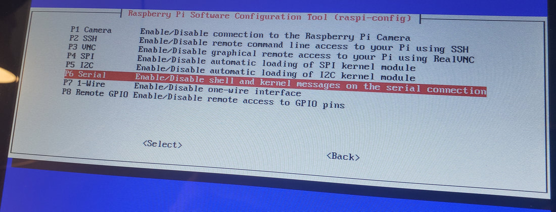
Select Serial,
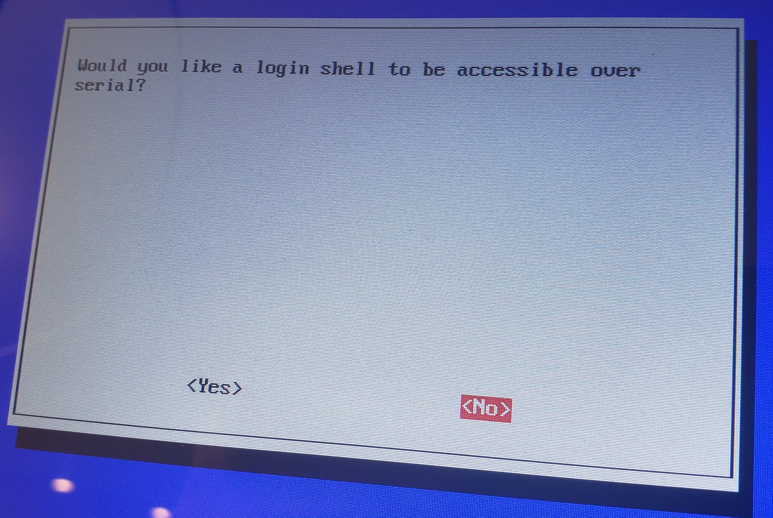
Select No to login shell over serial,
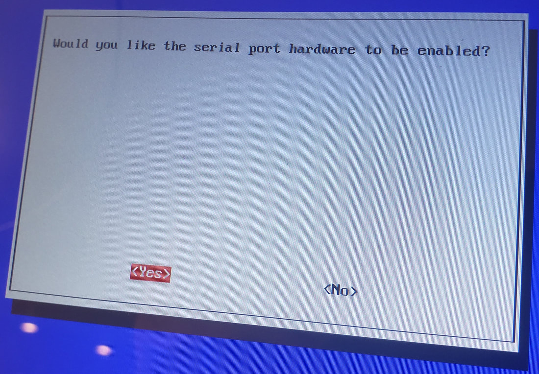
Select Yes to serial port hardware to be enabled.
Power up the RPI and access the config file. Information on how to access the config file can be found here: https://www.makeuseof.com/tag/edit-boot-config-file-raspberry-pi/.
Navigate the config file thus:
Select Interfacing Options,
Select Serial,
Select No to login shell over serial,
Select Yes to serial port hardware to be enabled.
 |  |  |  |
Reboot, close everything up, and power up the printer
In the OctoPrint interface access the OctoPrint menu, activating the new serial port by:
clicking the OctoPrint spanner,
clicking Serial Connection,
clicking General,
adding "/dev/ttyS0" to the Additional serial ports box.
Save, close, and return.
Then click on "/dev/ttyS0" in the Serial Port drop down menu.
Save again and close the tools menu.
Select "Restart OctoPrint" from the power menu and restart Octoprint.
When it reloaded, look for "/dev/ttyS0" in the Connection window. Select it and hit "Connect".
Disco.
I tried to make this post more simple than the previous post and this ends the tutorial.
Bonus: Increase the TX_BUFFER_SIZE to 128 in the firmware if you know how to do that.
A little bit more.
Now we know some things. Like, GND goes to GND, RPI TX (transmit) goes to board RX (receive), and RPI RX (receive) goes to board TX (transmit). This, I think, should hold true to similar relationships betweens RPIs and various boards.
Buck converter for the RPI.
I always provide power to my RPIs via the USB connectors, even if I'm using soldered USB connectors, which I actually prefer. Powering via GPIO bypasses the power regulation and fuse protection and why take that chance when we're soldering anyways? Here is a link to solderable Micro USB connector and USB-C connectors that I have used.
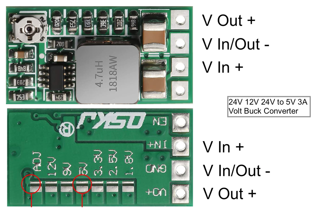
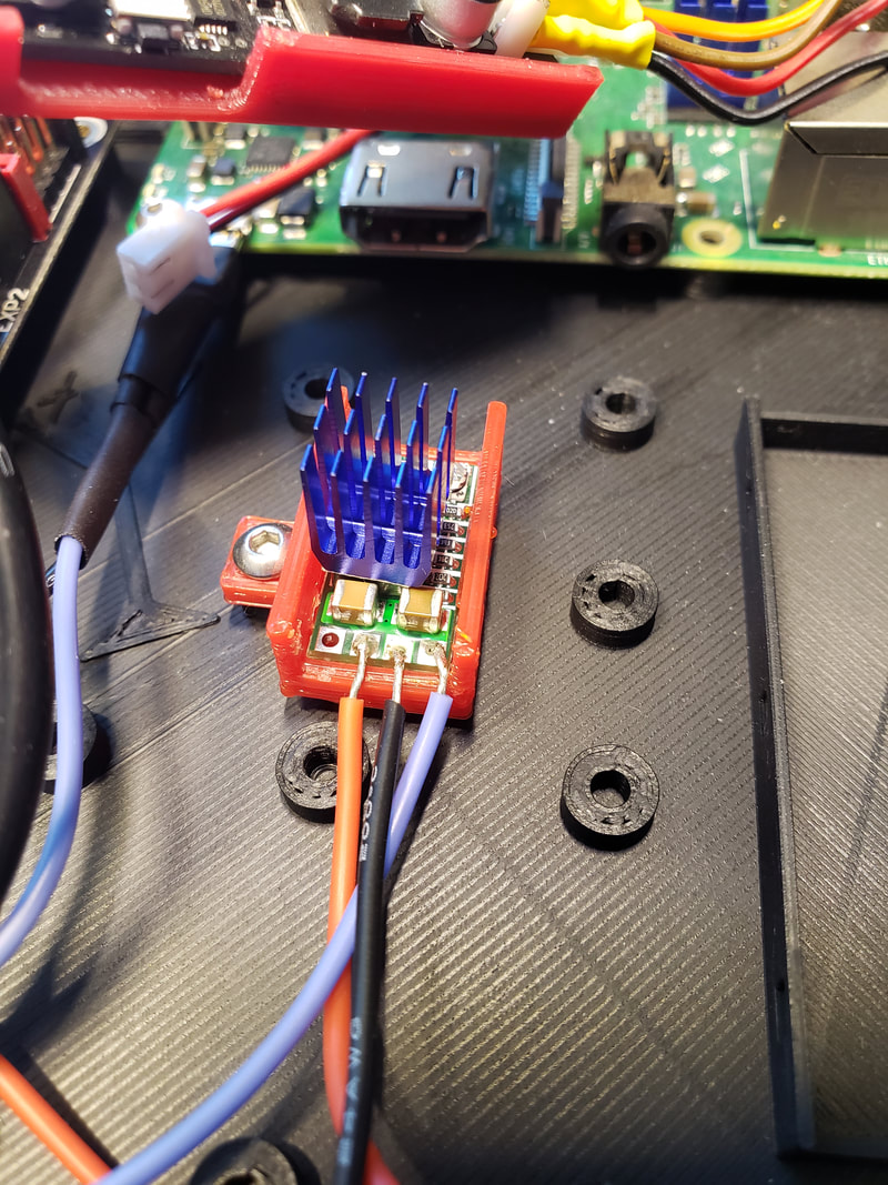
I reduced the voltage coming from the controller to 5V for the RPI using this buck converter. But, beware, the connections are mislabeled! This should help:
I always provide power to my RPIs via the USB connectors, even if I'm using soldered USB connectors, which I actually prefer. Powering via GPIO bypasses the power regulation and fuse protection and why take that chance when we're soldering anyways? Here is a link to solderable Micro USB connector and USB-C connectors that I have used.
I reduced the voltage coming from the controller to 5V for the RPI using this buck converter. But, beware, the connections are mislabeled! This should help:
 RSS Feed
